Zenith WIA and WIP Series Carburetters
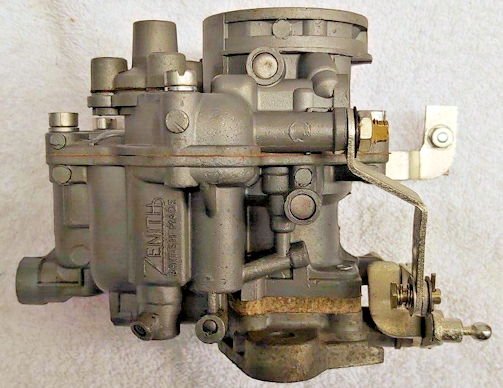
Zenith WIA and WIP Series Carburetters Features:
The following sections describe features and variations which are specific to models within the series WIA and WIP Carburetters, downdraught type having four main body assembly features, these are:
Upper barrel and float chamber cover. Main Body - Lower barrel, choke tube and float chamber. Throttle Body/Attachment Flange Assembly. Flanged Heat Insulator Block.
A mechanically operated accelerator pump, automatic strangler and lever type float are used. The purpose of the insulator block is to reduce the conduction of heat from the manifold to the float chamber: and so reduce the possibility of fuel vapour-lock occurring. Some models incorporate a depression incorporated power jet. The basic unit sizes are 34, 36 and 42 mm diameter choke. Variations in model detail are indicated in the type letters as shown here:
TYPE VARIATIONS
WIA
Initial Model. Three screw throttle body fixing.
WIA-2
Four screw throttle body fixing.
36 WIA-3
Air regulating screw. (NOT volume control screw).
42 WIA
Initial model.
42 WIA-2
Special short throttle body.
42 WIAT
As 42 WIA but with thermostatically operated strangler.
42 WIATD
As 42 WIAT but with throttle damper (for automatic gearbox).
36 WIP
Initial model. P indicates power jet omitted. Three screw throttle body fixing.
36 WIP-2
Four screw throttle body fixing.
36 WIP-3
Air regulating screw. (NOT volume control screw).
Dismantling and Assembly:
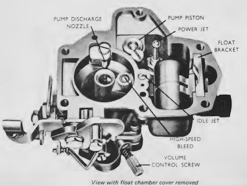
Remove float chamber cover retaining screws and lift off the cover to expose float chamber;this will give access to the Idle Tube High Speed Bleed, Accelerating Pump, Power Jet Float Needle, and Seating. The Main Jet is accessible after removing the Plug from beneath the float chamber; do not damagesealing ring and jet when removing them. If accelerating pump inlet and outlet valves are removed, take out the non-return ball valves beneath them for safety, otherwise they may drop out and get lost!
On assembly take care that the gaskets and power jet diaphragm are undamaged and that parts are correctly positioned when replacing the covers; make sure that the main discharge jet is replaced with the row of holes On the underside. When finally tightening the float chamber cover screws, do so in opposite and alternate pairs.
Petrol Level:
Generally speaking in 34 and 36 mm models (fuel inlet to float chamber bowl) the petrol level should be 16 mm (0.625 in) below the top face of the float chamber; where variations from this occur, the different level will be specified. When checking the level make sure that the carburetter is horizontal and that the float bracket is held down in its locating slot, to counter the float buoyancy.In the 42 WIA-2 models (fuel inlet to float chamber cover) the fuel level is 19 mm (0.75 in) below the top face of the float chamber.
Thermostat Unit for Air Strangler Control:
The use of a thermostatically operated strangler gives automatic choke control for cold-starting without need for the more usual manual method. The unit comprises a slef-contained assembly, fixed to the carburetter body, and engaging the strangler spindle; choke control is obtained by a combination of forces acting on a bi-metallic coil spring the outer end of which engages the strangler spindle operating lever. Constructional features, detailed method of operation and adjustments are as fully described for the Series VNT carburetter.
Idling Mixture Control:
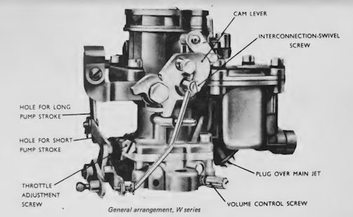
Normally idling mixture variation is obtained by the Volume Control Screw mounted in the side of the Main Body, but those carburetters having the in the type designation (e.g. 36 WIA-3) have Air Regulation Control. The screw for this adjustment is located in the float chamber cover.
Accelerating Pump:
Most models use the normal interconnecting link/lever operation of the accelerating pump. On some 36W units
however, a cam is used instead of the direct linkage. The profile of the cam is such that the greater proportion of the discharge from the pump occurs during the early part of the throttle movement; this is required on particular applications to obtain the best possible acceleration. (Certain applications of the W series include a modification which provides for a degree of enrichment of full throttle high speed mixture strength by drawing fuel from the pump circuit at times other than when accelerating.)
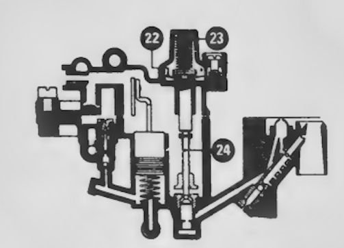
Power Jet :
Power jets 22, 23, 24, are fitted in WIA models; the jet is operated by diaphragm . control from the engine depression. At low throttle openings (high depression) the jet is closed; when the throttle is opened the depression is reduced, permitting the power jet to be opened by the diaphragm spring, allowing additional fuel to be fed to the main discharge jet.
Float Chamber Ventilation:
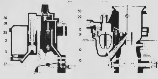
Ventilation of the float chamber is provided for in various ways. In some models this may take the form of an internal vent connecting with an impact tube projecting at an angle into the air intake and adjacent to the strangler flap. A simpler method consists of a direct ventto atmosphere via a groove cut in the float chamber cover. In the case of the 42 mm unit shown in Fig.32 a covered vent 29, 30 is used. Throttle Damper (for Automatic Gearbox): Closure of the throttle to idling position normally results in rapid reduction in engine rpm but for smooth operation when an automatic gearbox is fitted it is necessary to slow down the final stage of engine speed reduction. This is achieved by use of a damper consisting of a simple bellows unit placed in the throttle linkage line; its action delays the final throttle closure and brings the engine to idling speed gently.
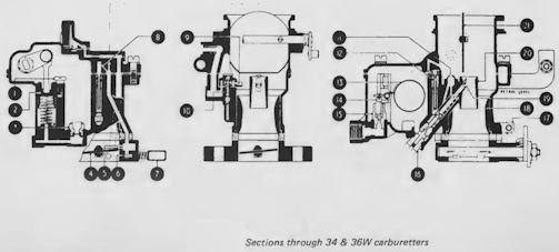
34 and 36W
1.Retaining screw
2. Accelerating pump piston
3. Inlet non-return valve
4. Throttle
5. Progression holes
6. Idling hole
7. Volume control screw
8. Air bleed hole
9. Discharge nozzle
10. Outlet non return valve
11. High speed air bleed
12. Idle tube
13. Float
14. Needle
15. Needle seating
16. Main jet plug
17. Throttle stop screw
18. Large venturi
19. Main discharge jet
20. Small venturi
21 Strangler flap
22. Power jet diaphragm
23. Compression spring
24. Power jet
Sections of 42W carburetter
2. Accelerating pump piston
3. Inlet non return valve
14. Needle
15. Needle seating
16. Main jet plug
19. Main discharge jet
25. Piston rod
26. Actuating rod
27. Link
28. Spring
29. Float chamber vent cover
30. Cover retaining screw