Morris Austin FG FM light truc
 |
|
|
Manufacturer: |
British Leyland Motor Corporation |
|
Production period: |
1959 to 1980 |
|
Engines: |
Gasoline 2.2 to 3.9 liters |
|
Payload: |
1.5-5 t |
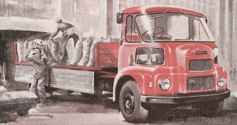
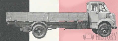
The Morris FG / Austin S200 and 404 (FG in export) was a light truck in cab-over-the-top construction, which the British Motor Corporation presented in 1959 as the successor of the lighter variants of the Morris FE / (Austin FE) and the Morris LC / (Austin 301) , The vehicles had an innovative, newly designed cab. After all commercial vehicles in the group were only marketed as BMC in 1968 , the model was now called BMC FG . The merger of BMC and Leyland Motors to British Leyland Motor Corporation in 1970 was again a name change to Leyland FG, As such, it was produced until 1980 and replaced by new body styles of Leyland Sherpa .
As Morris FG / Austin FG (S200 and 404) from 1959 to 1968, BMC FG 1968 to 1970, Leyland FG 1970 to 1980
In 1958, the redesigned Morris FF / (Austin S301 / 401/501) launched as a replacement for the heavier versions of the Morris FE / (Austin 301). 1959 presented BMC then the Morris FG / Austin S200 and 404 as the successor to the lighter versions and as a successor model for the even originally on a construction before the Second World War based Langhauber trucks Morris LC / Austin 301. During the FF chassis of the FE and received only a new body, the FG was completely redesigned. Only the concept of the separate front opening window in the front area resembled the FE. The difference between the Morris and Austin variant existed only in different radiator grills and brand emblems, as well as the name on the home market. In export, the Austin was often marketed as Austin FG.
When the FG was introduced, the concept of the cab was a quantum leap in commercial vehicle construction. The doors were mounted above the angled rear corners of the cab and struck behind as narrow suicidal doors . As a result, they barely protrude beyond the width of the cabin when opening and thus provided the advantage, similar to a sliding door. BMC marketed this under the term practical angle, popularly referred to as the "three-penny bit," based on the pre-decimal, a twelve-sided British coin. Even the entry itself was made easier by this door, because not more - as with many front handlebars usual - had to be climbed over the height of the front wheel to reach the door. According to investigations, the driver's entry and exit required only one third of the usual effort required of front-mounted drivers, which was considered a major advantage, above all in delivery service traffic. Not least was greatly facilitated by the sloping rear door window maneuvering.
NTRODUCED during early 1960, this series of trucks possesses a numberof interesting features. Not the least of these is the new style cab, with semi-rearward opening doors and transparentquarter panels. Additionally the FG cab, as it is known, has greater screen depth and curvature approximating to the now conventional full wrap-around type.curved "Street View" windows mounted at the front corners below the windshield. These helped the driver when parking, and also the dead angle was enormously limited. For example, when driving on pedestrian streets, smaller children were also to be perceived by the driver. The concept was rounded off by the shift lever and handbrake mounted on the right side of the driver's seat (right-hand drive version), which meant that there was always free passage in the cab.
Due to the angle design, however, there were also conceptual disadvantages. The room itself in the cabin was very narrow and therefore the seats were pretty narrow. Drivers had additional difficulty through the narrow doors and get out. In addition, the exhaust heat of the front engine together with the narrow cabin quickly made for stuffy air in summer. Probably also, therefore, the windscreens could be opened as in the predecessor, although such a design at that time actually went out of fashion.BMC finally refined the angle concept on the BMC 350 EA , which had sliding doors as standard. The "Street View" windows experienced a partial return at the Leyland Roadrunner , which had a small window on the passenger side in the front area below the windshield, giving the driver a view of the roadside.
From 1960, the series was marketed with payloads from 1 ½ to 5 tons. In addition to the flatbed also vehicles with box body were offered ex works. In addition, in cooperation with bodybuilders, there were also standard models in box van form for delivery services of all kinds. Thus, the FG was often seen as a Sunblest baker delivery vehicle or as a laundry delivery vehicle. These models had instead of a partition at the cabin end a sliding door. A big buyer of the FG models was British Gas.To mitigate the conceptual disadvantages of the FG, BMC submitted in 1961 for FM. Control of the vehicle is of the semi-forward pattern, and there is a range of alternative body types apart from the basic truck. there have been various options for engines over the years,at First either the 2199cc ohv petrol or the 2.2-litre diesel engine.Transmission of the drive follows the conventional pattern, through an hydraulically operated single dry plate clutch to a synchromesh gearbox and by two-stage propeller shaft to the spiral bevel final drive unit of the semi-floating rear axle.
As Morris FM / Austin FG K100 1961 to 1968, 1 BMC FM,1968 to 1970 and FM Leyland 1970 to 1980 .The Morris FM was essentially a modified version of the FG cabin with a larger front to allow the engine to be mounted further forward. This created more space in the cab, even for larger and more comfortable seats. Another possibility was to lock the (now larger) driver's seat by means of a rail centrally in the cab next to a foldable passenger seat, or a triple seat. However, the FM retained the two most striking features of the FG, the windows on the roadside and the specially arranged doors. The FM was delivered almost exclusively to the Post Office telephone, today British Telecom and the Royal Post.
Vehicle identification
On the first series vehicles are identified by chassis and vehicle serials. The chassis number is to be found stamped on a plate fixed to the front of the left-hand side chassis member. The vehicle number is stamped on a plate mounted inside the cab, just forward Of the left-hand door. The petrol engine number is stamped on the right-hand face of the cylinder block and the diesel engine number is stamped on the right-hand top face of the cylinder block.

Technical
-
Morris FG Technical details and specifications (1959-1980)
ENGINE
2.2-litre (Types 22V and 22F; also LEA and 22 C/U)
Type - 4-stroke; overhead valves; side camshaft
Cooling system - Water pump, fan and thermostat
Number of cylinders - 4 (bored direct in block)
Firing order - 1-3-4-2 (No. 1 at front)
Bore - 79.4mm. (3•125in.)
Stroke - 111.1mm. (4•375in.)
Cubic capacity - 2,199c.c.
Compression ratio - 6.8:1 pressure, 125 lb./sq.in.
Torque (lb.ft.) - 111 (22 V) ; 97 (22F) at 1,800 r.p.m.
Oil pressure (lb./sq.in.) - Normal running, 50; idling, 15
Petrol pump - A.C.-Delco mechanical 22V & 22F
Carburettor - Solex 32BIP LEA & 22 CIUTRANSMISSION DRIVE LINE:
Clutch (Borg & Beck)
Gearbox - 4-speed synchromesh
Gearbox ratios - 1.0;I-floating 1.57; 2.69; 4.63; R.5.93
Driving axles - 3/4 floating
Final drive ratio - 5.125 | 5.714
Crown wheel [pinion backlash - .010in. (max.)-Advanced Maintenance is available for members-
© Motor car History
Service
-
Morris FG Maintenance and Service Guide (1959-1980)
Engine removal
The engine Mountings At front, bonded rubber blocks are bolted up between
brackets on front plate and front cross members At rear, rubber blocks are bolted between bracket on gear-box extension and cross member. To remove with gearbox, remove radiator grille, drain cooling system and take out radiator matrix. Remove top and bottom water hoses to release matrix, lift out of vehicle. Disconnect battery, re-move seat cushions and inspection panels from engine cowl.Disconnect and remove, as necessary, all pipes, wires and controls to engine unit. Remove feed pipe from fuel pump and release exhaust down pipe at manifold junction. Remove front bumper complete with brackets and release front panel complete from cab. Support engine by means of cradle or trolley jack; alternatively a trolley packed to correct height with woodblocks. Release engine front mounting and remove front cross member from chassis.
Disconnect propeller shaft at gearbox drive flange, mark for re-assembly. Remove gearbox top cover and gearlever. Disconnect speedo drive cable
at gearbox end, and clutch fluid pipe at master cylinder.Replacement is a reversal of procedure .
-Advanced Maintenance is available for members-
