Rover 10 P1 (1933-1938)
 |
|
|
Manufacturer |
Rover |
|
Production |
1933 to 1938. |
|
Class |
Motor Car |
|
Produced |
9202 |
|
Body style |
saloon, coupé, open tourer |
|
Engine |
1.4 L straight 4 |
|
Transmission |
4-speed manual |
|
Wheelbase |
105 in (2,700 mm) |
|
Length |
152 in (3,900 mm) |
|
Width |
61 in (1,500 mm) |
|
Designers |
Maurice Wilks and Robert Boyle |
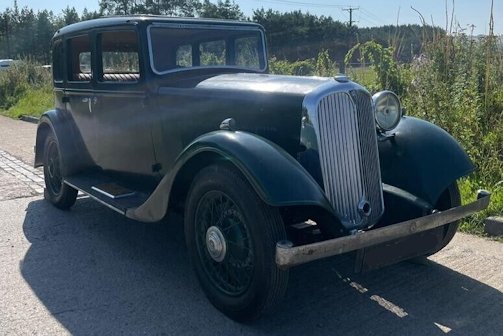
The Rover 10 P1 was a Motor car built in the 1930s by the Rover company in Great Britain. From 1933 to 1938 with the 4-Cylinder 1389 cc 1.4 litre engine .
History
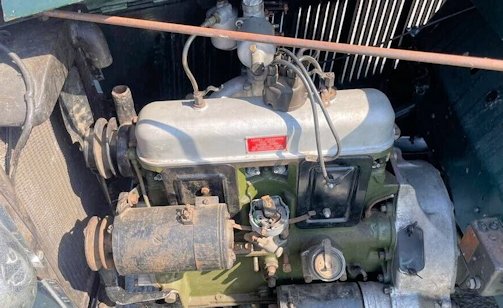
The new range for 1933 replacing the previous 10 and 10/25 model included a more upmarket Ten with also a new chassis that was also available to external coachbuilders and with now only Pressed Steel body built at the New Meteor Works, in Coventry England and fitted with a 1.4 litre engine. The Engine flexibly mounted, 66.5 mm. bore x 100 mm. stroke (with Treasury rating of 10.9 h.p.) this has overhead valves pump water circulation with automatic thermostat the lubrication by pressure from gear type pump.

The new chassis automatically lubricated by Bijur system the underslung chassis has a wheelbase 8 ft. 9 in. and track 4 ft. 3.5 in the saloon body with flush-fitting sliding roof Triplex glass throughout; finished green, green wheels.
For the electrics coil and battery ignition; ventilated dynamo; Lucas electrical equipment chromium-plated head, side and tail lamps; electric dual windscreen wipers and electric horn.
The transmission 4 speed and reverse easy-change gearbox with silent engagement, freewheel controlled from dashboard incorporated with gearbox operates on all forward gears; central remote gear control; single-plate clutch and open propeller shaft with spiral bevel final drive
For the steering and brakes, wheels and suspension a worm and nut steering system and Girling balanced mechanical brakes on all 4 wheels; 18 x 4.75 Avon Duo-Tread tyres on
detachable wire wheels; half-elliptic springs front and rear with also hydraulic shock absorbers front and rear.

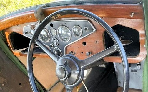
The saloon version features Inside green upholstery the equipment includes: centrally controlled windscreen, ventilating louvres at top of doors with built-in direction indicators with automatic return trip-speedometer The gauges include, clock; ammeter; combined electric petrol and oil gauge inside interior sun visors; mirror in near-side visor; interior light; driving mirror; roof parcel net; central folding and side arm rests to rear seat; body pulls; selected soft hide seating; specially improved seating springs; smokers' ash trays; driver-operated rear window blind; harmonic stabiliser; bumpers front and rear; folding luggage grid combined with rear bumper; spare wheel and tyre concealed by 1-piece cover; simplified jacking system; rear stop light and tool kit. Price, complete at £255
The "Ten" 4-Cylinder ROVER coupé came as a 4-seater coupé body with fixed head and flush-fitting sliding roof; finished maroon, maroon wheels and Upholstery soft hide seating; specially improved seating springs central folding and side arm rests to rear seat.
Equipment includes: chromium-plated head, side and tail lamps; electric dual windscreen wipers; centrally controlled windscreen; Triplex glass throughout; ventilating louvres at top of doors; built-in direction indicators with automatic return; electric horn; trip speedometer; clock; ammeter; combined electric petrol. and oil gauge;
interior sun visors; mirror in near-side visor; interior light; driving mirror; selected driver. operated rear window blind; smokers' ash trays; harmonic stabiliser; bumpers front and rear; built-in luggage compartment at rear; spare wheel and tyre; simplified jacking system; rear stop light; tool kit.
Price, complete, £280.
By 1935 the Rover programme comprised of the 10. 12 and 14 HP models. as well as Speed Fourteen and Speed Twenty Sports type cars. Prices ranged from £248 up to £495 .This model 10 was built up to 1938 .

Technical
-
Rover 10 P1 Technical details and specifications (1933-1938)
ENGINE
Four-cylinder
bore 66.5 mm.;stroke, 100 mm.
capacity, 1389 c.c.
compression ratio, 5-9 to 1
Contact-breaker gap, 0.012in.
Oil pressure, 301b. when engine is hot at 30 m.p.h.
Firing order: 1, 2, 4, 3.
carburetter.S.U. type C.N. needle on single-carburetter installation and No. 7 on twin-carburetter installations.TRANSMISSION.
Roper and Wreaks
Four-speed constant mesh, bolted to bell housing at four points
Free-wheel fitted at rear lubricated with gearbox.
Ratios :Top, 4.88 to 1 ; third, 7-45 to 1 ;second, 11.0 to 1 ; first, 19.1 to 1.
Clutch single-plate clutch
Hardy Spicer needle roller propeller shaft with Moss type; semi-floating rear axle.ELECTRICAL
Lucas 12-volt 53 a.h. battery with positive earth.
CVC Model C45PV/r dynamo belt-driven at 1 1/4 engine speed.
Manual and automatic centrifugal advance and retard mechanism
Lucas M418G starter with 11 teeth and 97 teeth on flywheel, clockwise rotation
RF50 control box with ammeter feed wire only leading to central terminal
A1 terminal to lights and ignition via regulator.
A2 terminal, via regulator, to screen wiper, horn and roof-lamp
A3 to ignition switch and A4 via ignition switch to stop lamp and direction indicators.STEERING.
Burman Douglas worm and nut with adjustment for end-float in the worm shaft at the cup-and-cone ball-race at the top of the column.
BRAKES
12in. cast iron drum Girling type brakes.CHASSIS:
Luvax shock-absorbers fitted until No. 701857, when a new type incorporating the adjustment and relief valve in one were fitted.Advanced Maintenance is available for the Rover 10 (1933-1938)
© Motor car History
Service
-
Rover 10 P1 Maintenance and Service Guide (1933-1938)
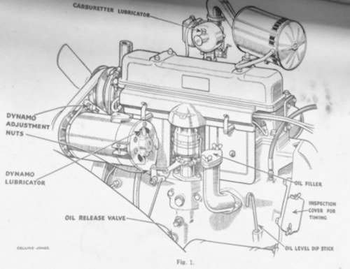
Check tyre pressures, oil carburetter controls. Examine level of oil in sump. Top up battery. Every 1,000 miles. Oil dynamo, distributor and handbrake lever.
Check gearbox and rear axle oil levels. Lubricate joints on controls and road springs.
Every 2,000 miles Drain sump and refill with fresh oil. Check clutch clearance and shock absorber levels. Check steering box lubrication and grease propeller shaft. Every 10,000 miles.-Examine brakes for wear: Renew -vacuum regulator on chassis lubricator and change oil in rear axle and gearbox.Clutch cable-operated to allow for engine movement. l in. dead movement must be maintained at. clutch pedal.
A slightly oiled-up clutch; may be cleaned by plugging holes at bottom of pit and washing out with half a pint Of petrol while the clutch
is " pumped " as the engine is turned over by hand.
Gits oil seal on each axle shaft and pinion shaft. Capacity of rear axle, 3.5 pints.Suspension adjustment: Every 250 miles. Pitching at the front end of the car can often be cured by slackening off the rear shock absorbers and tightening the front fittings slightly.
Valve clearances :When red plate is fitted to rocker box, 0.010in. When a black plate is fitted, 0.005in. These clearances are for all valves and should be made with the engine warm.
LUBRICATION and LEVELS
Capacity of sump, 8 pints.
Engine:Summer, S.A.E. 30 ; winter, S.A.E. 20
GEARBOX: After draining, the level should be checked after a short run. Capacity, 3 pints
Gearbox: S.A.E. 50
Steering box: S.A.E. 60Rear axle, S.A.E. 50Water capacity, 21/2 gallons.TYRES. WHEELS
18 x 4-75in. on wire wheels.Pressures are 281b. on front wheels and 301b. on rear.
ENGINE TIMING
On the flywheel are the marks FA4 or SF Adv., indicating firing point at full advance can be seen.The letters EP stand for exhaust peak and TDC indicates top dead centre for numbers 1 and 4. A cover on the near-side of the clutch pit is held by two 5/16in. nuts. Flywheel marks are visible below this cover.If the timing chain has been removed, rotate the camshaft in running direction until No. 1 . exhaust valve is fully open—a dial indicator on the rocker shaft is the only accurate way of ensuring this. Turn the engine until the EP mark on the flywheel is inline with the pointer in the aperture. Fit the timing chain.
To time the ignition turn the engine until the FA mark registers and both valves on No. 1 are closed. FA is 7 1/2 deg. or 3/4in. before TDC. The rotor arm of the distributor should now correspond with No. 1 H. T. terminal. The ignition control should be in the fully advanced position and the pinch bolt beneath the distributor head should be slackened and the head rotated until the points are just opening.Plugs: Lodge C.14 plugs with 0.015-18in. gap
Advanced Maintenance is available for the Rover 10 (1933-1938)
© Motor car History
