Vauxhall Ten 10-Four
 |
|
|
Manufacturer |
Vauxhall |
|
Production |
1937–1940 and 1946–1947 |
|
Class |
Motor Car |
|
Layout |
Front-engine, rear-wheel-drive |
|
Engine |
1203 cc ohv I4 34.5 bhp (1937–1940) |
|
Transmission |
3-speed manual |
|
Wheelbase |
94 in (2,388 mm) (1937–1940) |
|
Length |
155.5 in (3,950 mm) (1937–1940) |
|
Width |
61 in (1,549 mm) |
|
Curb weight |
2,016 lb (914 kg) |
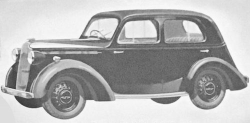
The Vauxhall Ten or Vauxhall 10-Four H-type is a low range small British sedan that was built pre and post war from 1937 to 1947.
History
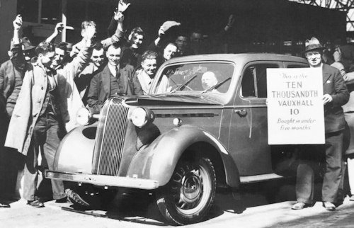
The Vauxhall Ten as a Standard or Delxe body Saloon first shown at the 1937 London Motor Show and also built in Australia as the HIY. However, the Second World War intervened and in 1940 the Luton plant was converted for the production of tanks and military trucks, so that the Ten could no longer be manufactured from this date but still with a large production produced up to 1940 of around 50,000. The name of the car corresponds to the taxable horsepower which then defined the class in which the car competed against its competitors. These were as the Morris Ten, Standard Ten and the Ford Ten Junior.
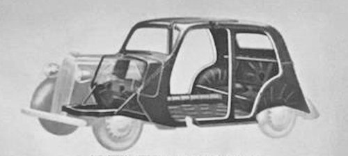
A key structural innovation was the self-supporting body, which was used by Vauxhall after the pattern of the 1935 Opel Olympia, the Vauxhall Ten became known in the company as the million-pound car, which reflected the extent of the company's investment in tooling for the new model to ensure a long production time and high production figures of future cars. The co-ordination of frame and body to give a structure which is not only of exceptional light- ness, thus assisting to give a lively and economic performance, combined with more body space, but is also allied with a structural strength equal to that of the conventional separate chassis frame and body construction. The chassis frame and body are integral with the exception of a short sub-frame' which supports the engine and front suspension units. This sub-frame is of welded steel construction, consisting of six- principal members, which include two channel section side members and two main cross members welded together. Forward extensions of the main cross sections are welded to the side members to form a hollow box section. The body itself is built with an inherent strength supplied by steel pressings so welded together to give a triangulated box girder construction not only along the base of the body as with a normal chassis frame, but also round the sides of the roof also. Transverse strength is obtained by box section girder welded to' the underside of the body and a perforated girder con- struction pressing welded into position and acting as a support for the front of the rear seat. Additional strength is supplied to the front of the car by tubular supports mounted toward s the forward end of the sub-frame and terminating at the base of the windscreen pillars, so forming a triangulated' construction between sub-frame and body.

Independent torsion bar front-wheel suspension, bodying special coil spring and lever compensators and double-acting shock absorbers, with the suspension units. All operating and there are no lubrication points. Rear suspension is by long semi-elliptic springs of conventional type, with rollers between the tips of the longer spring leaves to reduce friction and prevent squeak, and single-acting hydraulic shock absorbers. They are specially calibrated to meet the requirements of the car, and in combination with the front suspension, ensure an equally comfortable "Silentbloc" rubber bushes are' fitted to all rear spring shackles.
The Gearbox has three forward speeds and reverse. Helical cut gears and splines throughout for silent operation. Vauxhall controlled synchromesh. Silent constant mesh type second speed. Central ball gear change. Open tubular propeller shaft with needle roller bearings to both front and rear universal joints. Single dry-plate clutch with flexible centre for smooth engagement. Ball thrust clutch withdrawal mechanism for ease and silence. Clutch operation effected through a flexible chain to obviate engine movement on the rubber mountings being transmitted to the clutch pedal. Rear axle Semi-floating type. Spiral-bevel gears with straddle- mounted bevel pinion for strength and quietness. Detachable forged steel hubs keyed to tapered ends of axle shafts. Rear axle anchorages to springs insulated by means of rubber pads. Detachable ventilated disc-type wheels and 4.50 x 17 medium-pressure tyres. Large easily detachable plated hub covers.
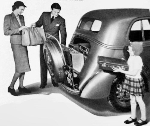
Inside the interior, body space allows generous rear seats accommodation for two adult passengers and a child, with ample leg room. The front seats, upholstered in leather, are of special "body conformity" design, and the whole of the body is made "drum-proof" and draught-proof and fume-resisting insulator is fitted as a bulkhead between the engine and body. The front windows are of Vauxhall '(No-draught" design, allowing passengers to control the amount of air entering or leaving the windscreen wipers Noiseless and reliable mechanical twin wind screen wipers are also driven from the engine camshaft. The steering Burman-Douglas worm-and-nut gear, all parts being of robust construction and having oil-bath lubrication with filler-plug replenishment; 3-spoke steel-core steering wheel with vulcanised rubber finish. Horn button integral with steering-wheel boss, and trafficator
switch and self-cancelling gear mounted on side of steering column for easy manipulation.

The Lockheed hydraulic brakes operating on all four wheels. brake shoes per drum with linkage arranged to produce semi-servo action on leading shoe, giving increased brake efficiency. The brake drums are of malleable iron, heavily ribbed on the exterior, and brake adjustment is achieved through a hole in the outer face of the brake drums, and can be performed via the hub covers without removing the road wheels. The hand-brake operates the same shoes as the foot-brake on the rear wheels only, by means of flexible steelebles. The hand-brake lever and ratchet are situated on the right-hand side of the instrument panel below the instrument board, within easy reach, but without impeding access to the driver's seat.
The performance of the Vauxhall Ten was stated in 1937 with 34 bhp (25 kW). It was originally released briefly in 1946 with the same ohv motor with 1203 cc capacity as before the war, but with lower power (and presumably lower compression due to poor fuel quality). Otherwise, the post-war model differed only slightly from the pre-war Vauxhall Ten. The British consumers, who had little money after the war, did not want small pre-war limousines, so the car did not succeed.

Technical
-
Vauxhall Ten Technical details and specifications (1937-1947)
ENGINE:
No. of Cylinders-4
Treasury Rating- 10 h.p.
cubic capacity- 1,203 (73.43 cu. in.)
B.H.P.- 34.5 at 3,800 r.p.m.
Firing order- 1-3-4-2
Bore-63.5 mm. 2.5in.
Stroke- 95 mm. 3.74in.
Compression Ratio- 6.5:1
Compression Pressure- 185
Oil pressure, lb. sq. in-Warning light operates below 101b. 25/35 average.
No. of crankshaft bearings- 3
Type of bearing (Crankshaft)- Steel backed, white metal liners; detachable
Camshaft drive (type)-Duplex Roller Chain 50 links
Valve timing markings-Steel Ball embedded-in Flywheel (4° B.T.D.C.)
Tappet type- Cylindrical, operating push rods and OH valves
Carburettor make- Zenith Downdraught, .30 V.I.G
Choke setting- 25 mmTRANSMISSION DRIVE LINE:
Clutch type- Single Dry Plate, 71/in. Spring loaded
Type of facing-Borg & Beck composition
REAR AXLE:Type of axle-Semi-floating
Type of drive- Spiral Bevel
Ratio- 5.14 : 1
Adjustment- Shims for pinion, adj. sleevo for diff. assembly
FRONT AXLE & STEERING: Camber- 1° to 2°
Turning circle- 35ft
Tyre size- 5.00in: x 16in. later 4.50in: x 17inBRAKES:
Type- Lockheed hydraulic
Type of linings- Raybestos C.P.2
Lining size (F. & R.)-
Lining size (F. & R.)-SPRINGS:
Type- Front, Helical Coil; Rear, Elliptic
Springs Length—Rear- 45in.
© Motor car History
Service
-
Vauxhall Ten Maintenance and Service Guide (1937-1947)
The Vauxhall "Ten" pre and Post war conforms to the following specification :
CAPACITIES:
Sump pints- 5
Gear Box pints-1
Rear Axle 'pints- 3
Radiator galls- 1 3/8
Petrol galls 6 3/4ENGINE:
1st O.S. Bore- + .003in.
Max. O.S. for boring- + .040in.
No. of compression rings- 2
Width of compression rings- .124in.
No. of oil rings- 1
Width of oil rings- .124in.
Inlet Valve working clearance (hot)- .006in.
Exhaust Valve working clearance (hot)- .013in.Carburettor of the Zenith down-draught type with acceleration pump, special part throttle economy device and inter-connected strangler and throttle control. Combined air-cleaner, silencer and flame arrester fitted ,to air intake. Rapid vaporisation of the petrol mixture in the induction manifold is obtained by a special thermostatically controlled heating chamber. When starting from cold the exhaust gases are directed round the centre portion of the induction manifold, a flap at the junction of the exhaust manifold preventing their progress through the exhaust system direct. A thermo-statically controlled valve opens the flap as the engine warms up and allows the gases to make their normal exit.
3-bearing crankshaft of high tensile steel with hollow crankpins and integral counterbalance weights running in steel-backed white metal bearings. Heat-treated steel connecting rods of H section split at small end and fitted with clamp bolt to grip gudgeon pin and suitably drilled at the big ends to give copious cylinder lubrication.
Detachable big-end Bearing liners of steel-backed white metal. Big ends split at an angle of 40° to facilitate removal of connecting rods through cylinder bores. Oval-ground aluminium alloy pistons, expansion controlled by steel struts across gudgeon-pin bosses. Lower ring groove drilled for oil return fitted with special high-pressure individually cast piston rings for oil control. Camshaft operating in three white metal steel-backed bearings. Cams designed with special quietening curves, and camshaft carrying an eccentric to operate fuel pump and two separate spiral gears to drive oil pump and distributor in tandem, and windscreen wiper respectively. Lubrication by gear-type pump in engine sump, providing positive delivery of oil to all bearings, pistons and valve mechanisms. For complete filtration of the oil a gauze strainer is mounted at the bottom of the oil pump surrounding the suction pipe, and an AC cartridge-type oil filter is mounted on the right-hand side of the engine towards the rear, adjacent to the screen wiper drive.
An electrically operated warning lamp mounted on the instrument panel indicates when the oil pressure system is functioning. Crankcase ventilation achieved by air being drawn through the oil filler cap and ejected through a ventilator pipe attached to the right-hand side of the engine and protruding through to the underside of the engine
Detachable, high-compression non-detonating cylinder head, with VAUXHALL overhead valves working in removable valve guides.Cooling system assisted by an impeller-type of water pump and fin, the two units being mounted on a common spindle and driven by a vee-belt and pulley. Water pump has "If-adjusting gland, and spindle is carried in sealed ball bearings. Temperature controlled by a thermostat mounted in the top water fitting, water being pumped into the cylinder head via a special tube which directs cooling water against the exhaust valve seats and sparking plug bosses. The water jacket is carried down to the full depth of the cylinders to allow for ample and uniform cooling of the cylinder bores.
ELECTRICAL:
Distributor rotation- Anti-clockwise
Distributor Manual advance- 8° micrometer adjustment
Distributor Automatic advance- 16° to 20° (centrifugal) Distributor Breaker gap- .010in.—.012in.
Plug make- A.C. K.9.V. end electrode
Plug gap-.037in.—.040in.
Firing order- 1-3-4-2
Ignition timing-To steel ball embedded in flywheel
Battery type- 6V. 68 A.H. Lucas STXW-IIE or Exide 3XT—13/11
Battery earth—pos. or neg- Positive 6-volt single-pole employing positive (+) earth return. Lucas compensated dynamo having automatic voltage control, regulating dynamo output in accordance with the condition of the battery. End plates of the dynamo ventilated to allow armature cooling by means of a fan. incorporated in the dynamo pulley. Fuse-box accessibly mounted on engine side of the dashboard. Foot-operated headlamp dipping switch, controlling pivotal near-side headlamp reflector' and temporarily blacking out off-side lamp during dipped period. Combined stop and tail lamp, stop lamp switch being hydraulically operated by brake system.Ignition by coil and distributor, allowing wide spark plug gaps to be utilised, thus assisting performance and petrol consumption. Distributor has automatic advance by centrifugal governor, with vacuum control from engine induction manifold and an external micrometer adjustment for varying fuel grades. The engine is mounted on two widely spaced rubber suppbrts at the front end and a twin rubber mounting at the rear, which effectively control any untoward engine movement during heavy load periods at low speeds.
PETROL TANK :
Petrol tank of 6 gallons capacity situated at the rear of the car, supplies petrol to the engine via a suction and delivery AC fuel
pump situated on the right-hand side of the engine and are driven from the engine camshaft
CHASSIS LUBRICATION.
Chassis lubrication by means of Tecalemit high-pressure grease nipples.
© Motor car History
