Zenith Series 30 VIG, 36 AND 42 VIS Carburetters Guide

Guide to the Zenith Series 30 VIG, 36 AND 42 VIS type Carburetters.
Features:
This series of carburetters is used over a wide range of vehicles and industrial engines of one to larger four litres capacity. The constructional arrangement comprises two main assemblies:
1.Main Barrel, with Choke Tube, Strangler Disc, Throttle Valve, Economy Device and Integral Float Chamber Cover.
2.Float Chamber, with Jets, Accelerating Pump and Emulsion Block.
All models are of the downdraught type, but vary in a number of ways. Some have fully automatic stranglers for easy starting, others have semi-automatic stranglers. Similarly, the quality of the slow-running (idling) mixture is controlled in one of two ways. There are also variations in throttle control lever position, fuel pipe and ignition control connections, and accelerator pump action as summarised below:
30 VIG MODEL VARIABLES
- CARB Type 5
Replaces 30VIG—2 and 3 Fuel Connection 5/ 16 in O/d Pipe. Throttle control sometimes at the side of the carburetter
STRANGLER TYPE Semi-Auto. -IDLE MIXTURE CONTROL Volume Control - CARB Type 6
Fuel Connection 1/4 in o/d Pipe.
STRANGLER TYPE Fully-Auto. -IDLE MIXTURE CONTROL Volume Control - CARB Type 7
Fuel Connection 1/4 in o/d Pipe.
STRANGLER TYPE Semi-Auto. -IDLE MIXTURE CONTROL Volume Control - CARB Type 8
Ignition control connection tapped 7 x 1.0 mm thread.
STRANGLER TYPE Fully-Auto. -IDLE MIXTURE CONTROL Air Regulation - CARB Type 9
STRANGLER TYPE Semi-Auto. -IDLE MIXTURE CONTROL Air Regulation - CARB Type 10
Ignition control connection tapped 7 x 1.0 mm thread.
STRANGLER TYPE Fully-Auto. -IDLE MIXTURE CONTROL Air Regulation - CARB Type 11
Has special accelerator pump follow-up action
STRANGLER TYPE Semi-Auto. -IDLE MIXTURE CONTROL Volume Control
Each of the above types has a direct-acting fuel-level float, ignition control connection, automatic depression operated economy device, mechanically operated accelerating pump and strangler/throttle interconnection for fast idling. In some applications a mixture spreader-bar will be found across the choke, in the plane of the emulsion beak, in others an additional bar is formed by an extended choke retaining screw (as shown); alternatively a longer emulsion block beak may be used, without
spreader-bars. The arrangement found will be that which gives the best results for the air inlet flow characteristics of the engine type concerned.
The working features described apply generally to 36 and 42VIS models too, except that in these the Economy Device is mounted in the float chamber cover, and the Idling Mixture Control is by air regulating screw. Where-as most units have an alternative hole location for accelerator pump stroke adjustment, the 30VIG-11 uses an adjustable stroke limiting stop arrangement concentric with the piston rod, on top of the float chamber cover.This is used in conjunction with a spring-loaded throttle lever which converts a positive action pump into a follow-up type.

Diagrammatic section of carburetter
1. Economy valve spring
2. Full-throttle air bleed
3. Air passage
4. Capacity Well
5. Slow running jet
6. Strangler lever
7. Strangler disc
8. Air drilling
9. Needle valve and body
10.Choke tube
11.Economy valve
12. Air drilling
13. Volume control screw
14. Float
15. Emulsion block
16. Fuel outlet
Economy Device:
On some applications it may have been found necessary to limit the air bleed to the jets at part-throttle. In these cases an orifice plug is fitted at the top of the capacity well to limit the amount of air from Passage 8, when the economy valve is fully open. The hole in the plug may
vary between 1.4 mm (0.055 in) and 4.0 mm (O. 157 in); if fitted as an original part, it should not be necessary to change the plug at a later date. A smaller orifice will offset the effect of the economy device to some extent, by enriching the mixture when the Economy Valve 11 is open but will have little influence when the valve is closed because at this condition the small permanent AirBleed 2 is the controlling feature.

Petrol Level:
The correct fuel level, with the float holding the needle valve closed against a delivery pressure of 1.5 lb/sq.in is 17 mm (1 1/16 in) down from the top face of the float chamber. This will be obtained if, when the cover is removed the petrol level is 22 mm (7/8 in) below the datum face; or 35 mm (1 3/8 in) with float also removed.

Dismantling:
The float chamber can be removed by first extracting the retaining bolts in the cover and supporting it underneath, withdrawing it horizontally from the body for about one inch. The float may now be removed exposing the assembly as shown in Fig.23. Where main and compensating jets exist with square recesses, they can be removed by using one of the float chamber retaining bolts which is squared off as a key for this purpose.
If the emulsion block is removed, on replacement check that the gasket is sound, tighten centre screws first, see that the aluminium seal washers are replaced on the three lower screws. The small hole adjacent to the head of the bottom screw is to assist in centre-punching to prevent the screw from working loose and dropping into the engine.
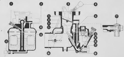
Diagram section of type 28G carburetter
1.Air regulating screw
2. (Inoperative)
3. Idling hole
4. Throttle stop screw
5 Throttle valve
6. Main air bleed
7. Fuel inlet with filter
8. Main discharge tube
9. Slow running jet
10. Choke tube
11. Dual floats
12. Needle valve
13. Needle valve and seat assembly
15 Float chamber drain
16. Float lever
17. Main jet plug
18. Strangler disc
19. Main jet
